- 您现在的位置:买卖IC网 > Sheet目录461 > IXTH12N90 (IXYS)MOSFET N-CH 900V 12A TO-247
I D25
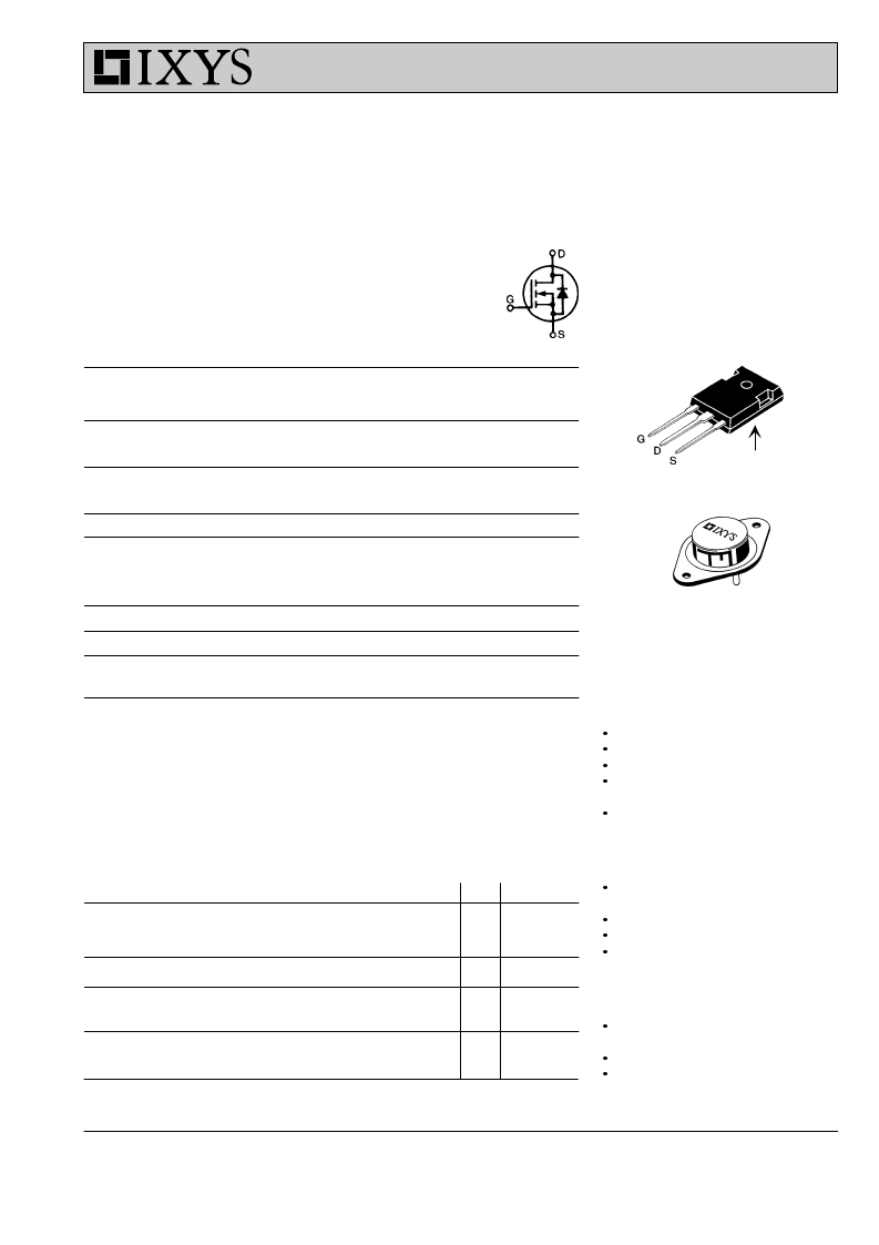
MegaMOS TM FET
N-Channel Enhancement Mode
IXTH 12N90
IXTM 12N90
V DSS = 900 V
= 12 A
R DS(on) = 0.90 ?
Symbol
Test Conditions
Maximum Ratings
TO-247 AD (IXTH)
V DSS
V DGR
T J = 25 ° C to 150 ° C
T J = 25 ° C to 150 ° C; R GS = 1 M ?
900
900
V
V
V GS
V GSM
I D25
I DM
P D
T J
T JM
T stg
Continuous
Transient
T C = 25 ° C
T C = 25 ° C, pulse width limited by T JM
T C = 25 ° C
± 20
± 30
12
48
300
-55 ... +150
150
-55 ... +150
V
V
A
A
W
° C
° C
° C
TO-204 AA (IXTM)
G
D (TAB)
M d
Weight
Mounting torque
1.13/10 Nm/lb.in.
TO-204 = 18 g, TO-247 = 6 g
G = Gate,
S = Source,
D = Drain,
TAB = Drain
Maximum lead temperature for soldering
300
° C
1.6 mm (0.062 in.) from case for 10 s
Features
International standard packages
Low R DS (on) HDMOS TM process
Rugged polysilicon gate cell structure
Low package inductance (< 5 nH)
- easy to drive and to protect
Fast switching times
Symbol
Test Conditions
Characteristic Values
(T J = 25 ° C, unless otherwise specified)
min. typ. max.
Applications
Switch-mode and resonant-mode
power supplies
V DSS
V GS = 0 V, I D = 3 mA
900
V
Motor controls
V GS(th)
I GSS
I DSS
V DS = V GS , I D = 250 μ A
V GS = ± 20 V DC , V DS = 0
V DS = 0.8 ? V DSS
V GS = 0 V
T J = 25 ° C
T J = 125 ° C
2
4.5
± 100
250
1
V
nA
μ A
mA
Uninterruptible Power Supplies (UPS)
DC choppers
Advantages
Easy to mount with 1 screw (TO-247)
R DS(on)
V GS = 10 V, I D = 0.5 I D25
Pulse test, t ≤ 300 μ s, duty cycle d ≤ 2 %
0.90
?
(isolated mounting screw hole)
Space savings
High power density
IXYS reserves the right to change limits, test conditions, and dimensions.
? 2000 IXYS All rights reserved
91593E(5/96)
1-4
发布紧急采购,3分钟左右您将得到回复。
相关PDF资料
IXTH130N10T
MOSFET N-CH 100V 130A TO-247
IXTH130N15T
MOSFET N-CH 150V 130A TO-247
IXTH130N20T
MOSFET N-CH 200V 130A TO-247
IXTH13N110
MOSFET N-CH 1.1KV 13A TO-247AD
IXTH13N80
MOSFET N-CH 800V 13A TO-247
IXTH14N100
MOSFET N-CH 1000V 14A TO-247
IXTH14N80
MOSFET N-CH 800V 14A TO-247
IXTH150N17T
MOSFET N-CH 175V 150A TO-247
相关代理商/技术参数
IXTH12N95
制造商:未知厂家 制造商全称:未知厂家 功能描述:TRANSISTOR | MOSFET | N-CHANNEL | 950V V(BR)DSS | 12A I(D) | TO-218VAR
IXTH12P25
制造商:未知厂家 制造商全称:未知厂家 功能描述:TRANSISTOR | MOSFET | P-CHANNEL | 250V V(BR)DSS | 12A I(D) | TO-218VAR
IXTH130N10T
功能描述:MOSFET 130 Amps 100V 8.5 Rds RoHS:否 制造商:STMicroelectronics 晶体管极性:N-Channel 汲极/源极击穿电压:650 V 闸/源击穿电压:25 V 漏极连续电流:130 A 电阻汲极/源极 RDS(导通):0.014 Ohms 配置:Single 最大工作温度: 安装风格:Through Hole 封装 / 箱体:Max247 封装:Tube
IXTH130N15T
功能描述:MOSFET 130 Amps 150V 12 Rds RoHS:否 制造商:STMicroelectronics 晶体管极性:N-Channel 汲极/源极击穿电压:650 V 闸/源击穿电压:25 V 漏极连续电流:130 A 电阻汲极/源极 RDS(导通):0.014 Ohms 配置:Single 最大工作温度: 安装风格:Through Hole 封装 / 箱体:Max247 封装:Tube
IXTH130N20T
功能描述:MOSFET 130Amps 200V
RoHS:否 制造商:STMicroelectronics 晶体管极性:N-Channel 汲极/源极击穿电压:650 V 闸/源击穿电压:25 V 漏极连续电流:130 A 电阻汲极/源极 RDS(导通):0.014 Ohms 配置:Single 最大工作温度: 安装风格:Through Hole 封装 / 箱体:Max247 封装:Tube
IXTH13N110
功能描述:MOSFET 13 Amps 1100V 0.92 Rds RoHS:否 制造商:STMicroelectronics 晶体管极性:N-Channel 汲极/源极击穿电压:650 V 闸/源击穿电压:25 V 漏极连续电流:130 A 电阻汲极/源极 RDS(导通):0.014 Ohms 配置:Single 最大工作温度: 安装风格:Through Hole 封装 / 箱体:Max247 封装:Tube
IXTH13N65
制造商:未知厂家 制造商全称:未知厂家 功能描述:TRANSISTOR | MOSFET | N-CHANNEL | 650V V(BR)DSS | 13A I(D) | TO-218VAR
IXTH13N80
功能描述:MOSFET 13 Amps 800V RoHS:否 制造商:STMicroelectronics 晶体管极性:N-Channel 汲极/源极击穿电压:650 V 闸/源击穿电压:25 V 漏极连续电流:130 A 电阻汲极/源极 RDS(导通):0.014 Ohms 配置:Single 最大工作温度: 安装风格:Through Hole 封装 / 箱体:Max247 封装:Tube